In the world of information technology, networking is the invisible backbone that connects everything. But how do different computers, built by different manufacturers, running different software, all manage to communicate flawlessly? The answer lies in a powerful, foundational concept: the OSI Model.
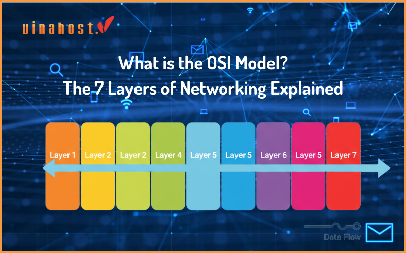
The OSI (Open Systems Interconnection) model is a conceptual framework that standardizes the functions of a telecommunication or computing system into seven distinct, abstract layers. Its primary goal is to ensure that complex network systems are interoperable – meaning systems from different vendors can communicate with each other seamlessly. It provides a universal language and a set of rules for networking design and troubleshooting.
In this guide, we’ll break down each of the seven layers, provide a simple way to remember them, and walk through a real-world example to see how it all works together.
1. An Easy Way to Remember the 7 Layers
Before we dive deep into the technical details, here’s a time-tested trick to remember the seven layers. Memorizing them is a rite of passage for anyone in IT, and these mnemonics make it easy.
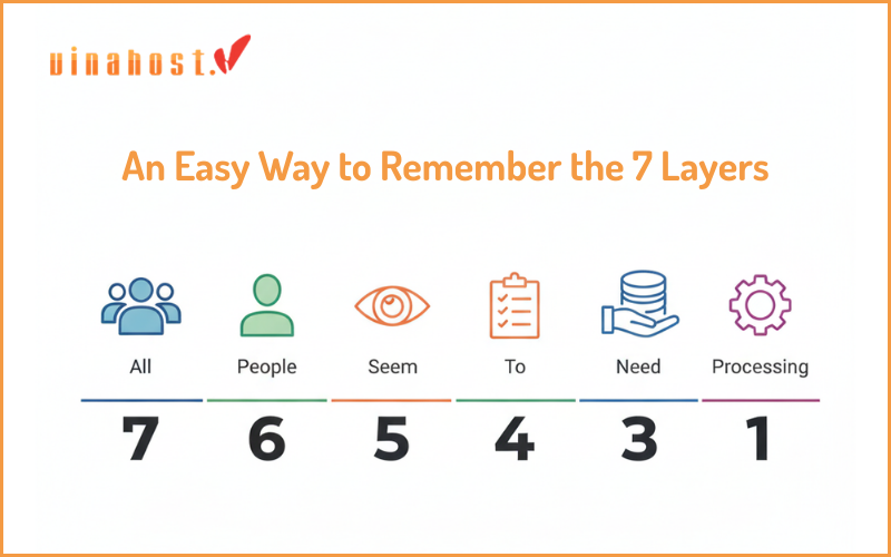
To remember the layers from Top to Bottom (Layer 7 down to 1), use this phrase:
All People Seem To Need Data Processing.
Now, let’s explore what each of those layers actually does.
2. The 7 Layers of the OSI Model
Here is a detailed breakdown of each layer, starting from the top (Layer 7) where the user interacts, down to the bottom (Layer 1) where data becomes a physical signal.
Layer 7: The Application Layer
Analogy: The User Interface
This is the only layer that directly interacts with the end – user. It’s the “human-computer interaction” layer, where applications can access network services. When you use a web browser, an email client, or a messaging app, you are interacting with the Application Layer.
Main Responsibility: To provide network services directly to user applications.
Key Functions: It identifies communication partners, determines the availability of resources, and synchronizes communication. It provides the protocols for user-facing services.
Examples: Your web browser (Chrome, Safari), email clients (Outlook, Gmail), and the protocols they use, such as HTTP/HTTPS, DNS, FTP (File Transfer Protocol), and SMTP.
Layer 6: The Presentation Layer
Analogy: The Universal Translator
The Presentation Layer is the translator for the network. It takes the data from the Application Layer and transforms it into a standard format that the rest of the model can understand. It also handles the reverse process, translating incoming data into a format the Application Layer can use.
Main Responsibility: To translate, encrypt, and compress data.
Key Functions:
Data Translation: Converts data between different character encodings (e.g: ASCII to EBCDIC).
Encryption/Decryption: Manages encryption to secure data during transmission and decryption upon arrival. This is where technologies like SSL/TLS operate.
Compression: Compresses data to reduce the number of bits that need to be transmitted, improving speed and efficiency.
Examples: SSL/TLS encryption, and data formatting like JPEG, GIF, and PNG for images or MPEG for video.
Layer 5: The Session Layer
Analogy: The Meeting Coordinator
The Session Layer is responsible for opening, managing, and closing the “session” or connection between two devices. It ensures that the conversation between applications is organized and synchronized.
Main Responsibility: To establish, manage, and terminate connections between applications.
Key Functions:
Session Management: Creates a session, keeps it active, and terminates it when the communication is complete.
Authentication & Authorization: Verifies that the parties in the session are who they say they are and have permission to communicate.
Synchronization: Places checkpoints in the data stream. If a connection is interrupted, the session can resume from the last checkpoint rather than starting over.
Examples: APIs (Application Programming Interfaces), NetBIOS (Network Basic Input/Output System).
Layer 4: The Transport Layer
Analogy: The Quality Control Manager
The Transport Layer is the first layer that truly deals with the end-to-end communication between the two systems. Its job is to take the data from the Session Layer, break it into smaller chunks called “segments,” and ensure it all gets to the other side reliably and in the correct order.
Main Responsibility: Provides reliable data transfer, managing flow control and error correction.
Key Functions:
Segmentation: Breaks large chunks of data into smaller, more manageable segments.
Flow Control: Manages the rate of data transmission to prevent a fast sender from overwhelming a slow receiver.
Error Control: Uses checksums to verify the integrity of the segments and re-requests any that are lost or corrupted (primarily a function of TCP).
Examples: TCP (Transmission Control Protocol), the reliable, connection-oriented protocol, and UDP (User Datagram Protocol), a faster, connectionless protocol. Learn more in our TCP vs. UDP comparison.
Layer 3: The Network Layer
Analogy: The GPS or Traffic Controller
The Network Layer is where the magic of routing happens. Its job is to move data packets across different networks – from your local network out onto the vast internet and to the correct destination. It determines the best physical path for the data to take.
Main Responsibility: To handle the addressing and routing of data across multiple networks.
Key Functions:
Logical Addressing: Assigns source and destination IP addresses to the data segments, creating “packets.”
Routing: Determines the optimal path to forward the packets from the source to the destination. This is the primary function of a Router.
Path Determination: Selects the best route among multiple available paths in a network.
Examples: The IP (Internet Protocol) is the most famous protocol at this layer. Routers operate at Layer 3.
Layer 2: The Data Link Layer
Analogy: The Local Mail Sorter
While the Network Layer gets the packet to the correct network, the Data Link Layer is responsible for getting it to the correct device within that local network. It manages node – to – node data transfer.
Main Responsibility: To provide reliable data transfer across a single physical network link.
Key Functions:
Framing: Takes the packets from the Network Layer and wraps them in containers called “frames.”
Physical Addressing: Adds the source and destination MAC Addresses (Media Access Control) to the frame. A MAC address is a unique hardware identifier for a network interface card (NIC).
Error Detection: Performs checks to detect errors that may have occurred at the physical layer.
Examples: Ethernet, Wi-Fi, and Network Switches operate at this layer.
Layer 1: The Physical Layer
Analogy: The Roads and Highways
This is the hardware layer. It’s all about the physical stuff you can touch: cables, connectors, and the electrical, light, or radio signals that represent the 1s and 0s (bits) of the data. This layer is responsible for the actual transmission of the raw bitstream over a physical medium.
Main Responsibility: To transmit and receive raw bit streams over a physical medium.
Key Functions: Defines the physical specifications for devices and media, including voltages, pin layouts, cable types, and data rates.
Examples: Ethernet cables (like Cat6), fiber optic cables, hubs, network interface cards (NICs), and radio frequencies for Wi-Fi.
3. How Data Flows Through the OSI Model: A Real-World Example
Let’s solidify this. Imagine you are sending a simple email.
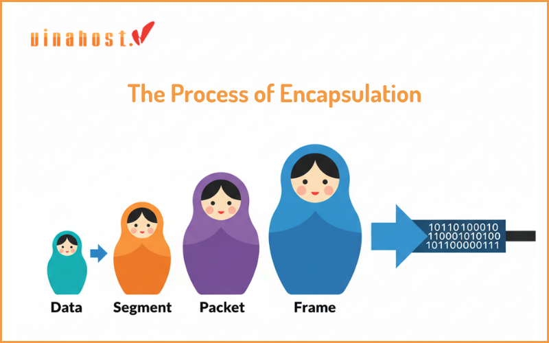
On Your Computer: The Process of Encapsulation
As your email data moves down the OSI stack, each layer adds its own header information (and sometimes a trailer). This process is called encapsulation.
Layer 7 (Application): You hit “Send.” Your email client uses SMTP to create the email data.
Layer 6 (Presentation): The data is formatted and potentially encrypted.
Layer 5 (Session): A session is established with the email server.
Layer 4 (Transport): The data is broken into TCP segments. Each segment gets a header with port numbers and sequence numbers.
Layer 3 (Network): Each segment is wrapped in an IP packet. A header with the source and destination IP addresses is added.
Layer 2 (Data Link): Each packet is put into a frame. A header with the source and destination MAC addresses is added.
Layer 1 (Physical): The frame is converted into a stream of 1s and 0s (bits) and sent as electrical signals over your Ethernet cable.
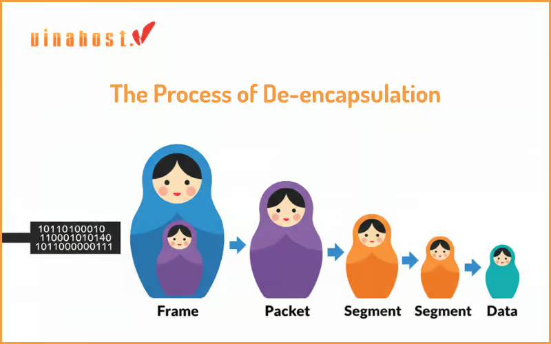
On the Email Server: The Process of De – encapsulation
The server receives the signals and moves the data up the stack, stripping away the headers at each layer. This is called de – encapsulation.
Layer 1 (Physical): Receives the electrical signals and converts them back into bits.
Layer 2 (Data Link): Reassembles the bits into a frame, checks the MAC address, and removes the Layer 2 header.
Layer 3 (Network): Checks the IP address and removes the Layer 3 header.
Layer 4 (Transport): Reassembles the segments in the correct order and removes the Layer 4 header.
Layer 5, 6, 7: The data is passed up through the Session and Presentation layers until it arrives at the Application layer, where the email server can process your incoming email.
4. Is the OSI Model Still Used? OSI vs TCP/IP
This is a critical question. While the 7 – layer OSI model is the universal standard for teaching and understanding networking, the modern internet doesn’t strictly implement it.
In practice, the internet is built on the simpler TCP/IP model. The TCP/IP model is a more practical, implemented framework that combines several OSI layers.
The OSI Model is a reference model. It’s perfect for troubleshooting (“This looks like a Layer 2 problem”) and for standardizing protocol development.
The TCP/IP Model is a functional model. It describes the protocols that are actually used in today’s networks.
Here is a simple comparison of how the layers map:
| OSI Model (7 Layers) | TCP/IP Model (4 Layers) |
| 7. Application | \multirow{3}{*}{Application} |
| 6. Presentation | |
| 5. Session | |
| 4. Transport | Transport |
| 3. Network | Internet |
| 2. Data Link | \multirow{2}{*}{Network Access} |
| 1. Physical |
5. Putting It All Together: The OSI Model in a Real-World VPS
Understanding the OSI model isn’t just an academic exercise; it provides the foundation for making critical decisions about IT infrastructure that directly impact performance, security, and user experience. A perfect real-world example where all seven layers work in harmony is a Virtual Private Server (VPS).
When a business or developer chooses to use a VPS, they are essentially renting a virtualized environment that perfectly encapsulates the OSI stack:
The Provider’s Responsibility: The VPS hosting provider manages the complex lower layers. They are responsible for the Physical Layer, the Data Link Layer and the Network Layer. This allows the customer to benefit from a robust and reliable network foundation without needing to manage the physical hardware.
The Customer’s Control (Layers 4-7): The user has full control over the upper layers within their VPS instance. You manage the Transport Layer by configuring firewall rules for TCP/UDP ports. You control the Session, Presentation, and Application Layers by installing your own software: web servers (like Apache or Nginx), databases, setting up SSL/TLS encryption (Layer 6), and deploying the applications (Layer 7) that your end-users will interact with.
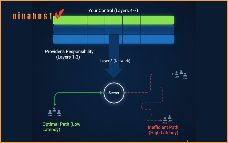
This clear division of responsibility is powerful, but understanding the model also helps in choosing the right VPS. The performance of your application heavily depends on the Network Layer (Layer 3), particularly on routing efficiency and the physical distance data must travel. To minimize latency and provide the best experience, you must host your services as close to your users as possible.
For businesses targeting audiences in Southeast Asia, for instance, choosing a high-performance VPS Malaysia can significantly improve website loading times and application responsiveness. Similarly, deploying services on a VPS Laos provides a strategic advantage for reaching users within the Mekong region, ensuring data packets travel the shortest, most efficient path. Choosing the right server location is a direct, practical application of understanding the principles of the OSI model.
5. Conclusion
While you may not interact with the OSI model directly every day, it is the silent, logical foundation that makes modern networking possible. By breaking down the monumental task of global communication into seven manageable layers, it provides a powerful roadmap for building, managing, and troubleshooting the networks that connect our world. Understanding these layers is the first step toward mastering the intricate and fascinating language of data communication.
 Tiếng Việt
 English
 简体中文
简体中文


